[DEPRECATED] Updated Version here.
ROS navigation stack drives the robot by publishing velocity commands to /cmd_vel topic using geometry/Twist messages. The base controller on the Teensy board receives the twist messages through rosserial_python and translates the velocites to motor commands. A PID controller maintains the robot’s speed by calculating how much PWM signal must be generated to spin each motor based from the total error over time. Errors are derived by comparing the actual motor’s speed to the desired speed sent by navigation stack.
This section will show you how to tune the PID controller with lino_pid, wire up the components, and upload the base controller’s code on the Teensy board.
2.1 Building the hardware
Before wiring up the components, build a base made up of wood plank, acrylic sheet or any material that you can mount the electronics, motors and wheels. Some ideas for your robot base:

Storage box from Ikea. (Photo by Ikea)

Plastic enclosure box. You can easily find this on hardwares.

Tin storage box. (More metallic look)
Once you have a base, wire up the components as shown below (2.1.2).
2.1.1 Parts List
1 x XV-11 Lidar with Controller or any supported 2D lidar.
1 x Ubuntu Installed laptop/desktop (Development Computer)
1 x Radxa Rock Pro (Robot’s computer) or any supported dev boards
1 x Teensy 3.1 Board or latest.
1 x GY-85 IMU
2 x L298 Beakout Board or any motor driver that has PWM (EN) and input pins (IN1 and IN2)
1 x Breadboard or Prototyping Board
1 x 12V Battery (Preferably 3S Li-Po Battery)
1 x Caster Wheels (only for 2WD)
2 x Robot Wheels (only for 2WD)
4 x Robot Wheels (only for 4wD)
4 x Mecanum Wheels (only for Mecanum Drive)
1 x Servo (only for Ackermann Steering)
1 x Robot Chassis
2.1.2 Wire up
The hardware is designed to be modular and scalable in the future. All the platforms are built using a L298N motor driver (2 Amperes) and motors with built-in encoders. If your robot requires a much higher motor rating or higher encoder resolution, you can opt for components with better specification and use the same pin assignments as below without rewriting the firmware.
ENCODER
Not all motors have built-in encoders especially high torque motors. Shall you need to use an external encoder, you can use a bi-shaft motor to leave the spare shaft for the encoder or use a pulley to drive both the wheels and the encoder.

A photo of a bi-shaft motor connected on a wheel (left side) and a wheel encoder (right side).
Motor with built-in encoder


External Encoder


MOTOR DRIVER
If you’re replacing the motor driver with a higher specification, make sure the motor’s power draw is less than the motor driver’s power rating. You can use the same firmware and follow the same pin assignments below as long as your new motor driver has PWM, IN1, and IN2 pins. Below is an example how to choose an alternative for your motor driver. The photo on the right (VNH5019 driver) has a continuous current rating of 12A and the same pinout as L298N breakout board.


2WD Hardware

4WD and Mecanum Drive Hardware

Ackermann Steering Hardware

Updated: February 2, 2017: The wirings have been changed for L298 and BTS7960 motor driver compatibility. Please refer to the previous wiring diagram and firmware.
2.2 Uploading the Arduino codes
2.2.1 Define robot’s specifications
Before uploading the codes, identify and define your robot’s specification on the config file.
On your robot’s computer, open and edit the config.h:
cd ~/catkin_ws/src/
nano linorobot/arduino/firmware/lib/config/lino_base_config.h
and change the values of the variables accordingly (*You don’t need to define k_p, k_i, and k_i for now).
Make sure to define variable DEBUG as 1 for debugging later.
The firmware is configured to work on L298 motor driver. Uncomment BTS7960_DRIVER and comment out L298_DRIVER if you are using a BTS7960 motor driver.
If you are unsure what is the encoder’s PPR (COUNTS_PER_REV) – you can check the encoder’s total count from bringup.launch’s terminal (see 2.3.1). Get the recent count and rotate the wheel 360 degrees:
PPR = abs(RECENT_COUNT – INITIAL_COUNT)
If you have the encoder and motor’s specification:
PPR = MOTOR_GEAR_RATIO * ENCODER_RES
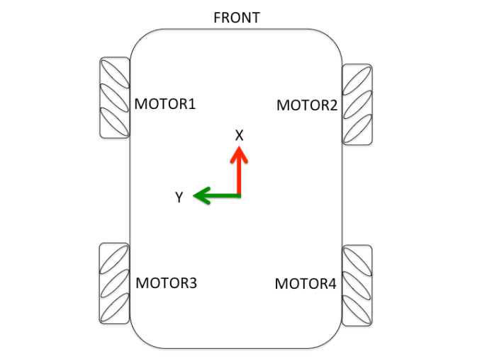
#define DEBUG 1

#ifndef LINO_BASE_CONFIG_H
#define LINO_BASE_CONFIG_H

#define L298_DRIVER
// #define BTS7960_DRIVER

#define DEBUG 0

/*BTS7960 PID
#define K_P 0.05 // P constant
#define K_I 0.5 // I constant
#define K_D 0.1 // D constant
*/

#define K_P 0.6 // P constant
#define K_I 0.3 // I constant
#define K_D 0.5 // D constant

// define your robot' specs here
#define MAX_RPM 45 // motor's maximum RPM
#define COUNTS_PER_REV 4000 // wheel encoder's no of ticks per rev
#define WHEEL_DIAMETER 0.15 // wheel's diameter in meters
#define PWM_BITS 8 // PWM Resolution of the microcontroller
#define BASE_WIDTH 0.43 // width of the plate you are using

// ENCODER PINS
// left side encoders pins
#define MOTOR1_ENCODER_A 15 // front_A
#define MOTOR1_ENCODER_B 14 // front_B

// right side encoders pins
#define MOTOR2_ENCODER_A 12 // front_A
#define MOTOR2_ENCODER_B 11 // front_B

#ifdef L298_DRIVER
  //left side motor pins
  #define MOTOR1_PWM 21
  #define MOTOR1_IN_A 20
  #define MOTOR1_IN_B 1

  //right side motor pins
  #define MOTOR2_PWM 5
  #define MOTOR2_IN_A 8
  #define MOTOR2_IN_B 6
#endif

#ifdef BTS7960_DRIVER
  // left side motor pins
  #define MOTOR1_IN_A 22
  #define MOTOR1_IN_B 23

  // right side motor pins
  #define MOTOR2_IN_A 6
  #define MOTOR2_IN_B 5
#endif

#define STEERING_PIN 22

#endif
2.2.2 Upload the codes
The first time you upload your codes using platformio, it will prompt if you want to install the framework (ie. ‘teensy’) you are using. Press ‘y’ to proceed with the installation. Once the framework is installed, plug in the Teensy board to the robot’s computer and upload the codes:
cd ~/catkin_ws/src/linorobot/arduino/firmware
platformio run --target upload
2.3 Running the robot
2.3.1 Drive the robot
Now check if the wheels’ direction is correct. Lift the robot off the ground so the wheels can move freely.
If you’re building a mecanum drive robot take note of the roller’s orientation below:
On your robot’s computer, run the launch file to start ROS and rosserial_python:
roslaunch linorobot bringup.launch
On your development computer, run teleop_twist_keyboard:
rosrun teleop_twist_keyboard teleop_twist_keyboard.py
Follow the instructions on the terminal to move the robot.
For the Ackermann steering robot, the angular velocity is translated to steering angle since it can’t rotate in-place. Check if the front wheels steer left and right when you press ‘j’ and ‘l’ respectively.
2.3.2 Check the encoder readings
Next, check if the encoder readings are correct from the terminal where you ran bringup.launch. All encoder readings must increase as you drive forward, and decrease as you drive in reverse.
2.3.3 Troubleshooting
If the wheel’s direction is wrong as you drive forward or reverse, swap the pin assignments for MOTOR*_IN_A and MOTOR_IN_B in the config file found in section 2.1.1.
If the encoder returns opposite results, swap the pin assignments for MOTOR*_ENCODER_A and MOTOR_ENCODER_B in the config file found in section 2.1.1
If the front wheels on the Ackermann robot are steering in the opposite direction, swap the operators in steer() function’s “if” conditions.
if(steering_angle_deg > 0)
 {
 steering_angle = map_float(steering_angle_deg, 0, 90, 90, 0);

 }
 else if(steering_angle_deg < 0)
 {
 steering_angle = map_float(steering_angle_deg, 0, -90, 90, 180);
 }
2.4 Calibrating PID
In order to maintain the speed sent by navigation stack, your PID controller has to be tuned properly. You can use lino_pid to tune your PID constants.
On your robot’s computer, open 2 new terminal windows:
Run bringup.launch:
roslaunch linorobot bringup.launch
Run pid_configure:
rosrun lino_pid pid_configure
On your development computer, open 2 new terminal windows:
Run teleop_twist_keyboard:
rosrun teleop_twist_keyboard teleop_twist_keyboard.py
Open rqt:
rqt
Once the dashboard is open, import the .perspective file by clicking Perspective > Import and choose lino_pid.perspective from lino_pid package: ~/catkin_ws/src/lino_pid/lino_pid.perspective
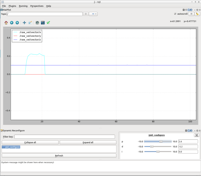
Click pid_configure under Dynamic Reconfigure window and slide the parameters at the bottom right window to tune your PID constants. Drive the robot and see the results from the graph.
Here are some tips how to configure your PID constants(Page 13).
Once your PID constants are tuned, record the values and edit the config file:
cd ~/catkin_ws/src/
nano linorobot/arduino/firmware/lib/config/lino_base_config.h
and change the values of K_P, K_I, K_D to the PID values you have recorded.
Upload the updated PID constants to the Teensy board:
cd ~/catkin_ws/src/linorobot/arduino/firmware
platformio run --target upload
3. Odometry
Great! The robot base is done and ready for dead reckoning. Please proceed to odometry page.
